Classic Mini Clutch and Flywheels Explained

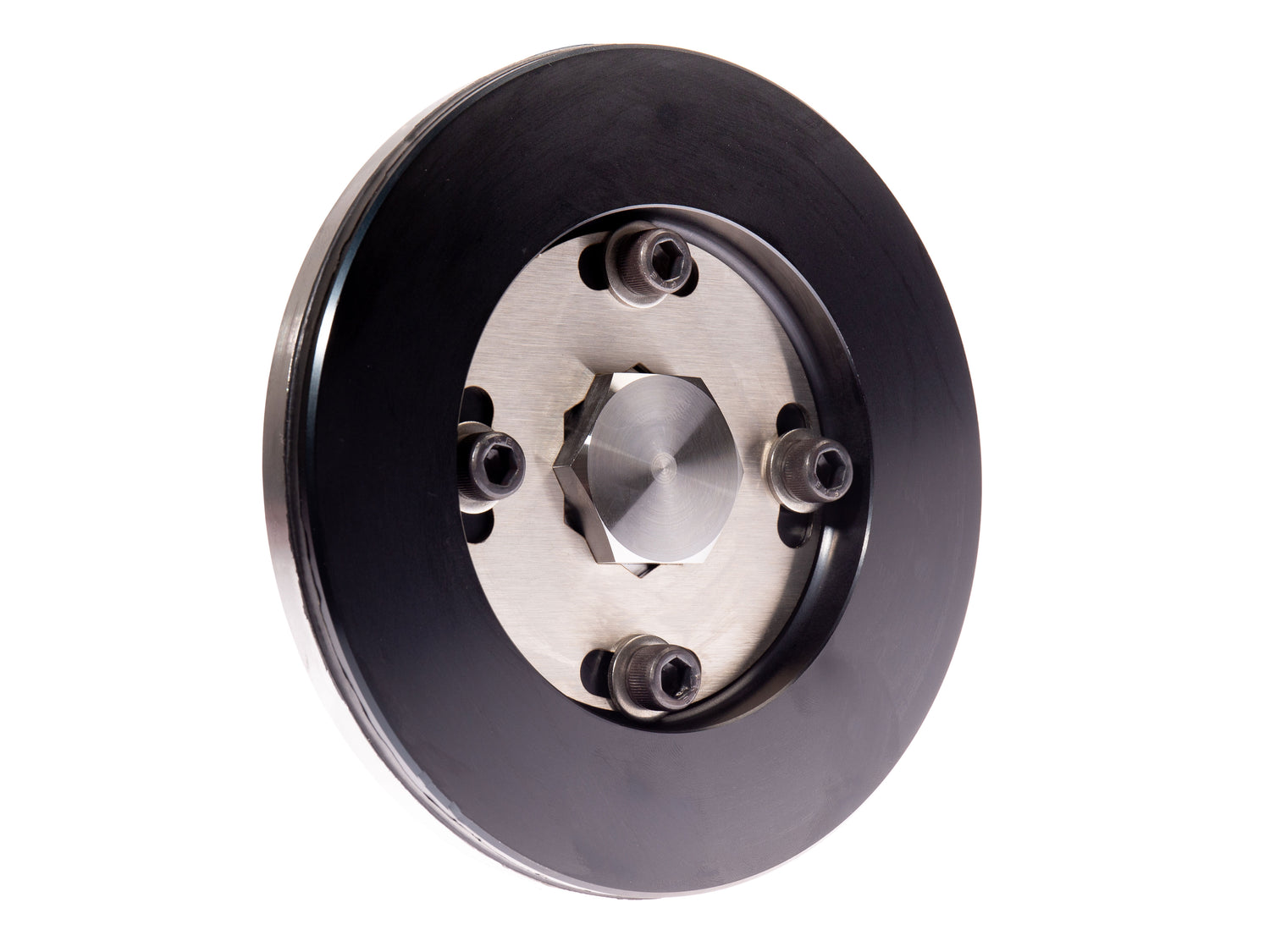
MED has been producing classic Mini lightweight steel flywheels for over 20 years, and today it remains one of our specialist areas, as we build and balance around five complete kits a day on our rig.
Why are the kits so popular? It's a relatively easy bolt-on upgrade, and upgrading the flywheel makes a surprising improvement to the performance any Mini, whether that's an early 1960s Morris Mini Minor or the very latest Rover Mini Cooper Sport. 
It helps that we're one of only a few suppliers who dispatch a complete balanced flywheel package, which is something we'd highly recommend choosing over buying the parts individually.
But we'll come back to that next time, when we look at performance upgrades.
First let's take a look at how the Mini's clutch and flywheel setup actually works - an unusual arrangement by modern standards, with the transmission mounted below the A-Series engine.
What is a flywheel for?
In layman's terms, the suck, squeeze, bang, blow process of a four-stroke four-cylinder engine creates some pretty uneven forces upon the classic Mini's crankshaft as it rotates within the engine.

The engine fires every 180 degrees of crankshaft rotation, the 'power stroke' of the piston and conrod driving down upon the crankshaft below. The 'compression stroke' sees force in the opposite direction as the ingested fuel and air mix is squashed in the sealed chamber.

Spun up to speed by the engine, the mass of the flywheel works as a vibration damper to smooth out harmonics from the contained chaos of internal combustion, while its inertia keeps the engine spinning at a steady RPM.
The flywheel's second purpose is to provide a friction face upon which to grip the clutch drive plate and transmit engine power to the gearbox below.

Thirdly, the flywheel has ring gear attached to its outer diameter, with teeth to engage with the electric starter motor and get things up and running.
Therefore the flywheel is essential to the classic Mini A-Series, like any internal combustion engine.
Are all classic Mini flywheels the same?
Put simply, no. The first MkI Minis had quite an antiquated spring-loaded clutch system that worked adequately on a basic 850 engine, but led to some reliability issues as performance levels increased.

From around 1964, when the Mini Cooper S had unexpectedly taken on the world as a rally super star, a new and improved system was devised with a two-piece flywheel, back plate and diaphragm spring.
Today the early flywheel system is given the catchy name, 'pre-Verto', but it's more accurately described as a classic Mini diaphragm-style clutch and flywheel.

The two-piece flywheel featured a separate steel mounting boss for the crankshaft taper, with a big heavy cast iron flywheel bolted on the outside.
An update arrived in the mid 1970s, perhaps for cost saving or perhaps for ease of production, with a one-piece flywheel design.
It remained cast iron and heavy, but on the plus side, as engine performance increased over time, firmer clutch diaphragms were developed to improve the torque holding ability.

From the early 1980s, with the advent of the A+ engine came the Verto-branded clutch and flywheel, and the system was retained until the end of production in 2000. It too can be modified with an uprated cover to handle higher torque loads.
How does a classic Mini flywheel fit?
Unlike most cars, the Mini's flywheel has a tapered internal bore and a matching tapered nose section of the crankshaft, tightened up with a large flywheel bolt and keyed washer on the end. 
As the bolt is torqued up, the flywheel is seated securely on the matching taper section of the crankshaft, locking the two components in place.
The classic Mini is quite unusual with this taper fitting on the crankshaft to flywheel.
On a typical setup where the transmission mounts to the end of the engine, such as the A-Series MG Midget, below, the flywheel mounts directly to a matching boss, with two dowels for alignment.

This design would not work with the Mini's unusual drop gear arrangement mentioned earlier, as the primary gear would not pass over a large mounting boss.

When the assembly is then fitted to the engine, the clutch plate slides over the centre spline on the crankshaft-mounted primary gear - one of three gears that transmits power down to the gearbox.

Drive from the crankshaft is transmitted through the clutch and down via a trio of drop gears to the gearbox below. Three gears are required to ensure the transmission turns in the same direction as the crankshaft.

The downside of a taper crankshaft fitment, especially apparent on higher performance engines, is that if the flywheel works loose for any reason, it can and often will fret on the taper and become friction-welded in place.

In the best case scenario, a decent flywheel puller will remove the offending flywheel and the crankshaft can be lightly cleaned up. In the worst case, this can render both the crankshaft and flywheel unserviceable.
How to avoid a Mini flywheel fretting on the crankshaft
To avoid this happening, we would highly recommend having the flywheel backplate centralised to the flywheel, and the complete assembly balanced to within 1 gram. On EN40B steel crankshafts, make sure to use an EN24T steel flywheel.
When fitting, try the following procedure;
- Remove the release bearing thrust plate and wire clip.
- Gently lap the flywheel to crankshaft taper.
- Carefully remove all traces of lapping paste.
- Refit flywheel and tighten F/W bolt, ensure correct fitment of keyed washer.
- Lock the engine in position with a Mini flywheel locking tool.
- Torque the MED pre-Verto flywheel bolt to 130lb/ft, to seat flywheel on the crankshaft taper.
- Undo the bolt, apply a drop of standard-grade thread lock to the thread and re-torque to 130lb/ft.
How does the classic Mini clutch work?
With the clutch is in its engaged state, a large diaphragm spring within the clutch cover applies pressure to the outside of the flywheel. The thickness of this spring denotes how much pressure is applied. This is a competition 'orange' cover.

The flywheel back plate is fixed directly to this cover with three bolts, the two components then bolted to the flywheel via spring steel drive straps. There's six fixing bolts in total.
Pressure from the diaphragm spring upon the flywheel pulls the backplate firmly towards the flywheel, the two parts gripped together by the clutch friction plate that's sandwiched in-between.

When the flywheel rotates with the crankshaft, so does the clutch plate - they're locked together thanks to the spring, the drive straps and back plate. The strength of this bond determines the torque holding ability of the clutch assembly - too much torque and the clutch plate will slip.

Depressing the clutch pedal, the hydraulically-controlled clutch arm levers a plunger with a bearing into the thrust plate on the clutch cover, as shown above with the clutch housing removed.
And here's how things look once on the car with one of our heavy duty clutch arm kits...

The clutch arm and plunger presses against the thrust plate on the clutch cover, which effectively pushes against the diaphragm spring and moves the back plate away from the flywheel. In turn this releases the clutch plate's grip.
So with your foot on the clutch pedal, the clutch friction plate no longer grips between the flywheel and back plate and no drive is transmitted down through the drop gears. You can now select a gear before re-engaging the clutch.
In words it's complicated - in reality it's pretty simple!
What's the difference between Verto and pre-Verto?
Verto clutches work in a similar way to the early style, bound by the constraints of the Mini's crankshaft taper fitting and drop gears, but they look more similar to a modern day clutch setup.
Although no longer branded 'Verto', the name has stuck.

The large belleville washer-style clutch diaphragm spring is replaced by multi-finger spring, attached to the clutch cover/back plate.

Rather than the flywheel mounting directly to the crankshaft taper, a tapered central boss attaches to the clutch cover, and in-turn the flywheel bolts on to this.

To disengage the clutch there's a top hat sleeve that presses against the spring via the clutch arm and release bearing mechanism.

The Verto clutch arm is shorter, with the slave cylinder mounted at a downwards angle on a bracket attached to the clutch housing.
When the Verto system arrived, so did the pre-engaged starter motor. Early Mini flywheels with an inertia starter need to have 107 teeth on the ring gear, pre-engaged Mini and Metro have 129.

The idea behind this updated clutch came with the changing target market for the Mini and Metro. By the 1980s, the cars were marketed more as runabouts for the ladies than rally cars for burly blokes, and the standard Verto clutch cover and lever arm gives a much lighter clutch pedal.

Whereas on the early clutch setup, the flywheel makes up the main mass of the assembly, on the Verto system it's the cover, so assembly and balancing is a slightly different procedure.

Firstly we fit the centre boss to the clutch cover and balance this as a unit. We then bolt the flywheel to the clutch cover assembly and balance again as a complete kit.

When the final production Minis moved to fuel injection from 1991, the Verto flywheel was modified with a reluctor ring on the inside face to work with the crank position sensor mounted near the starter motor.
The SPi Mini flywheel has two gaps in this sensor ring, the MPi Mini flywheel has four.
Look out for the next blog posts soon, where we'll look in much more details at all of the improvements that can be made to the classic Mini's clutch and flywheel setup, including weight reduction, torque holding and balance.
Related blog posts:
Weight reduction of the classic Mini flywheel
Improve torque holding of the classic Mini clutch
June 2024


